LEGO-ifier

Printed plates that click any board onto Pip · 8 mm stud grid

← Pip the robot
Works completely offline
First time? Calibrate before a big print

Print a small one first and make sure it fits

Every printer, filament and frame is a little different. Five minutes of test printing saves a plate that will not go in, or falls out.

1
Print the calibration strip

Five snap-off tabs, each with one stud, from 4.80 to 5.20 mm. The dots count the size: 1 dot is the smallest, 3 dots is your current setting. They sit on a thin handle beside each tab, below the face that touches the frame, so only the stud is tested.

2
Press each tab into your frame

Into a hole of the grid (or the underside of a LEGO brick). The right one goes in with a firm push and holds upside down, but comes out by hand.

3
Type in the winner

Each dot is 0.1 mm. Two dots = 0.1 mm smaller than now, four dots = 0.1 mm bigger. Put that number in Stud diameter.

4
Check with a 2 × 2 plate

A 16 × 16 mm plate with four studs: it tests the spacing too. If it fits, every plate you make with these settings will.

01 / Define the plate

Enter your dimensions

The outer size of the plate: usually the size of your board, or a little bigger. Everything updates automatically.

mm
mm
mm
mm
mm
Recent designs

The grid always uses 8.00 mm center-to-center, independent of stud diameter.

Your result
3 × 26 total studs
8.00 mm between all neighboring centers
02 / Check the layout

Live plate preview

Seen through the plate from the board side. Blue = the first stud (for Fusion).

First stud Pattern copies Bolt hole↔ 8 mm center spacing
🎯 Place the CENTER of your first circle here
3.50 mmfrom the LEFT edge →
5.00 mmfrom the TOP edge ↓
Measure to the circle's center dot, not the outside of the circle. Start at the top-left corner; pattern right and down.
03 / Get the plate

Download it, or draw it

The STL is ready to slice. Fusion 360 users can rebuild it from the values below.

Ready-to-print STL

Studs, plate and bolt holes in one file. It prints studs up (the board side flat on the bed): 0.2 mm layers, 3 walls, PLA or PETG. Flip it over to fit it: studs go down into the frame.

23 × 18 mm, 6 studs
or in Fusion 360
▾   RECTANGULAR PATTERN×
◉ 1 selected   ×
↔   ↕   Select 2 directions
▤   Extent ⌄
☐
▼ Direction 1 · horizontal (↔)
3
16.00 mm
➜ One Direction ⌄
▼ Direction 2 · vertical (↕)
2
8.00 mm
➜ One Direction ⌄

Sign rule: These distances are absolute extents. If Fusion's preview goes outside your rectangle, put a minus sign in front of that distance. The correct direction is always from the first stud toward the inside. Bolt holes are not in the pattern: add them after the studs (the copied values include where).
04 / Mount your board

The plate clicks into the grid. The board goes on top.

Use whatever is in the drawer. These are the three ways the first Pip's boards are held on.

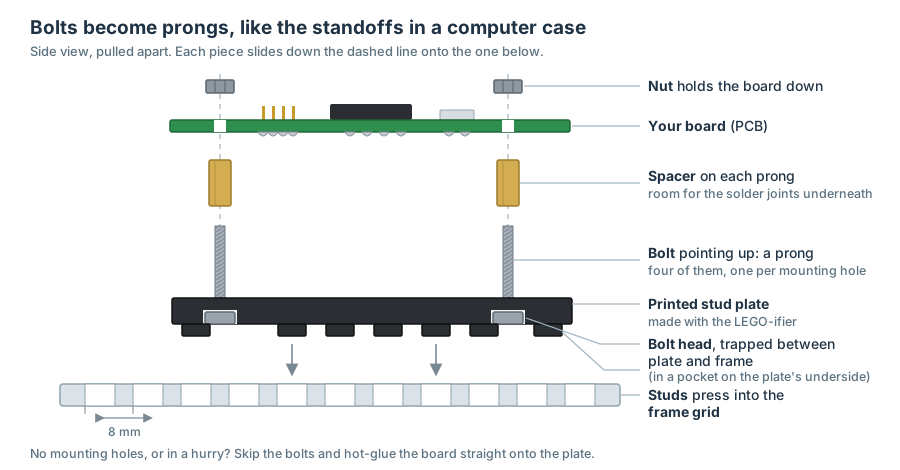
Exploded side view: the frame grid at the bottom; the printed stud plate above it with studs pressing down into the grid and four bolts pointing up through the plate like prongs, their heads trapped between plate and frame; a spacer on each prong for room under the board; the board on the spacers; a nut on each prong.
Board has screw holesBolts as prongs

Push four bolts up through the plate from underneath, heads in the pockets. They stick up like prongs. Slide a spacer (or a stack of nuts, or a cut piece of straw) onto each one so the solder joints under the board have room, drop the board on, and finish with a nut. It is the same idea as the standoffs in a computer case.

In a hurry, or no holesHot glue

Turn off the bolt holes, print the plate, and glue the board straight onto it. Put the glue on the parts of the board with nothing underneath, or add a few blobs as feet if there are solder joints in the way. It holds well and peels off with a little rubbing alcohol.

OptionalSquishy TPU pads

If you are not in a rush, print small washers in TPU and put them between the plate and the board. They take up a little vibration and stop a bolt from cracking a board. Honestly, they do not add much: bolts and spacers are plenty.

Building it in Fusion 360 instead

Do exactly this in Fusion

1
Sketch your plate

Draw the rectangle at 23 × 18 mm and extrude it 3.00 mm.

2
Draw just one stud

On the plate's face: circle diameter 5.00 mm. Place its center 3.50 mm right, 5.00 mm down from the top-left corner.

3
Sketch → Rectangular Pattern

Select that circle. Choose the horizontal and vertical directions. Set Distribution = Extent. Enter the quantities and distances shown above; point the pattern into the plate.

4
Finish Sketch → Extrude

Click OK, finish the sketch, select all circular profiles, then Extrude 1.80 mm outward using Join to make raised studs.